


Agotado
SKU: 000626
S/ 70,00
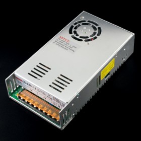
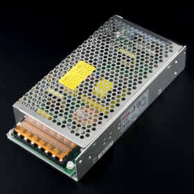
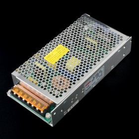
Fuente conmutada de 24V 4.2A 100W. Ideal para proyectos de automatización industrial y domótica.

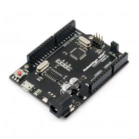
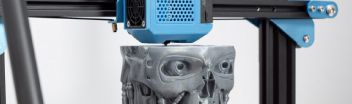
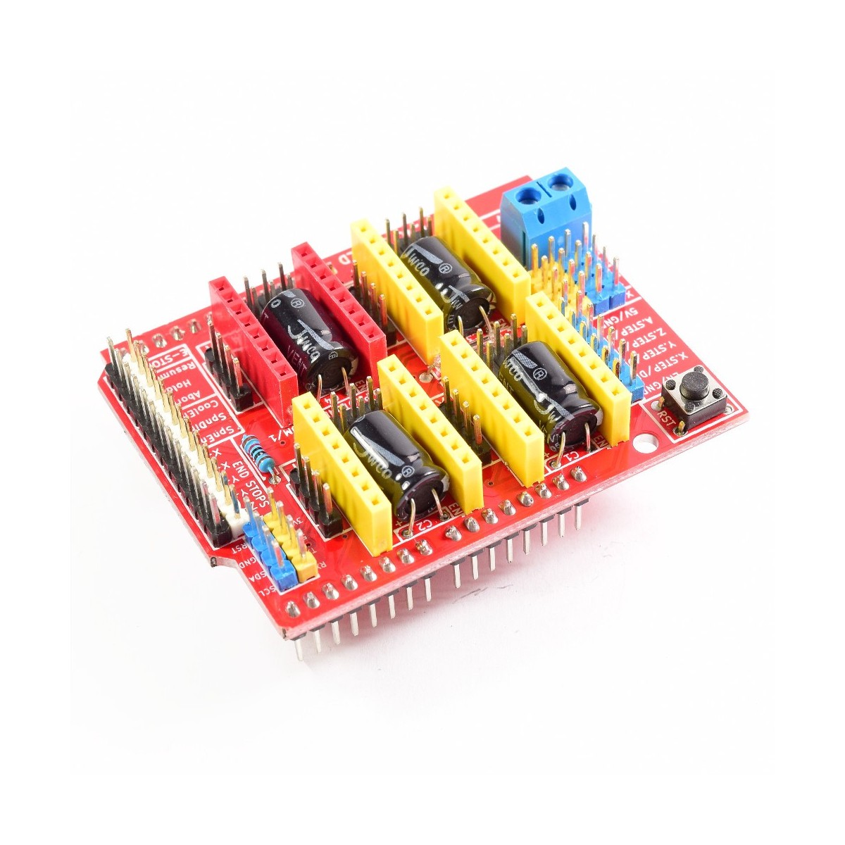
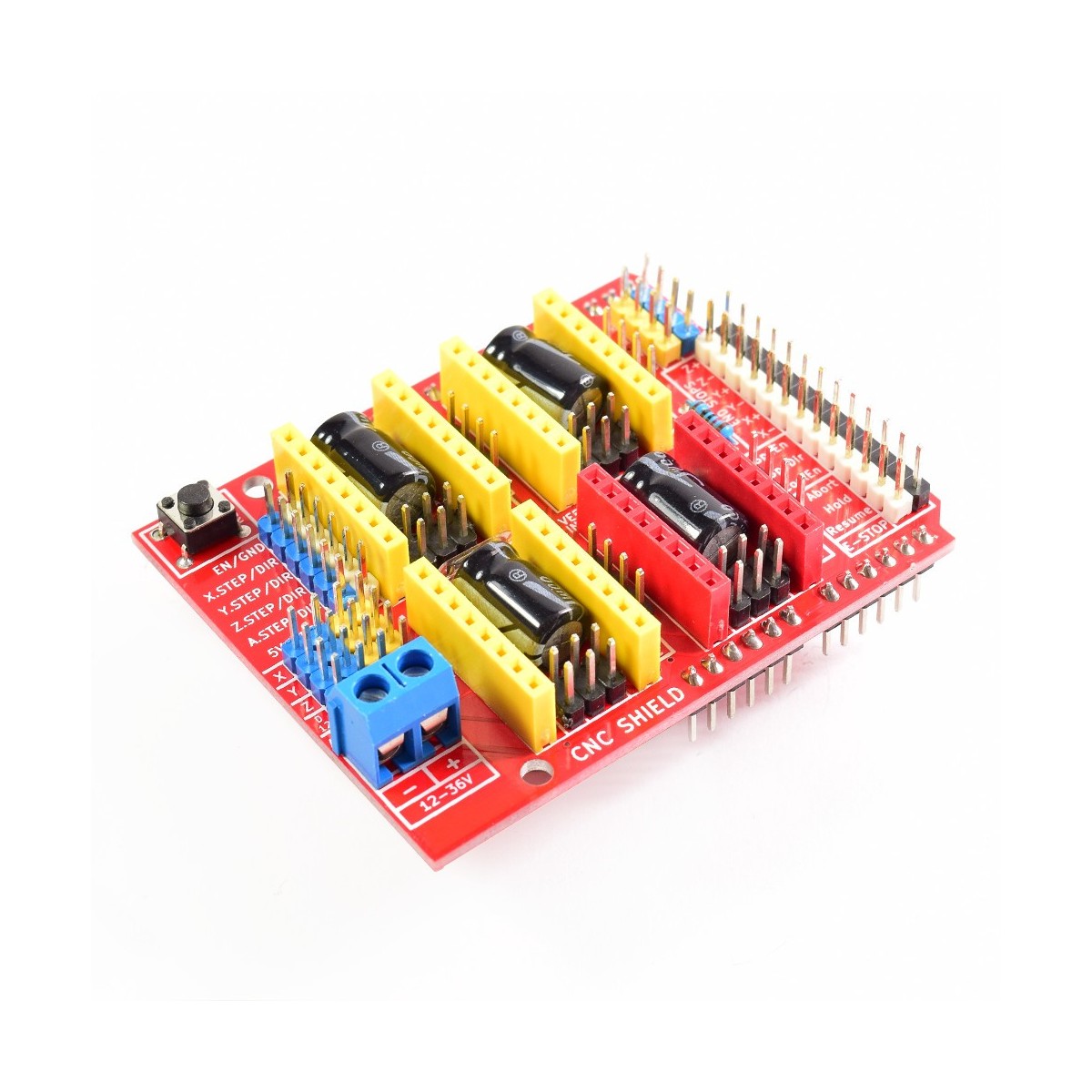
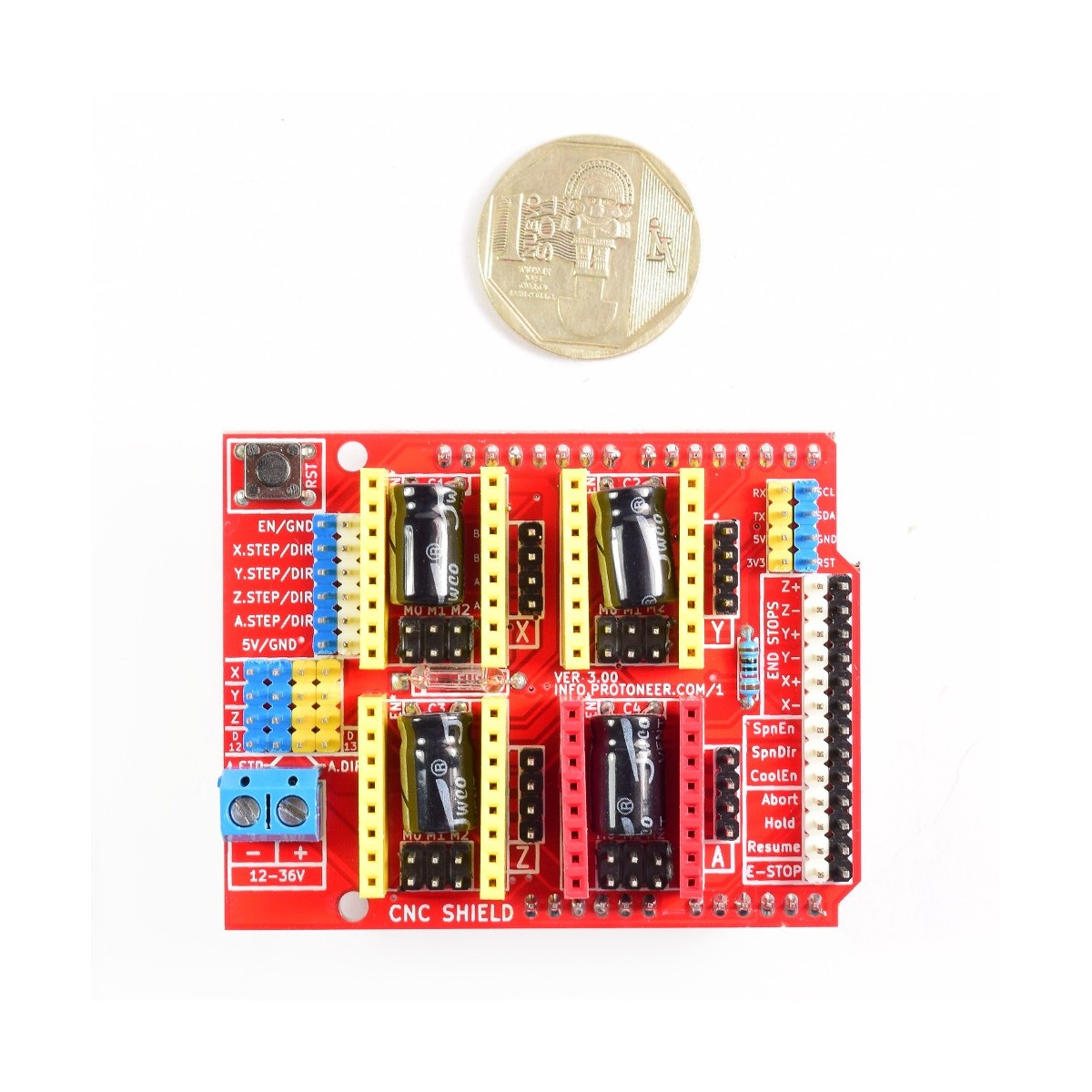
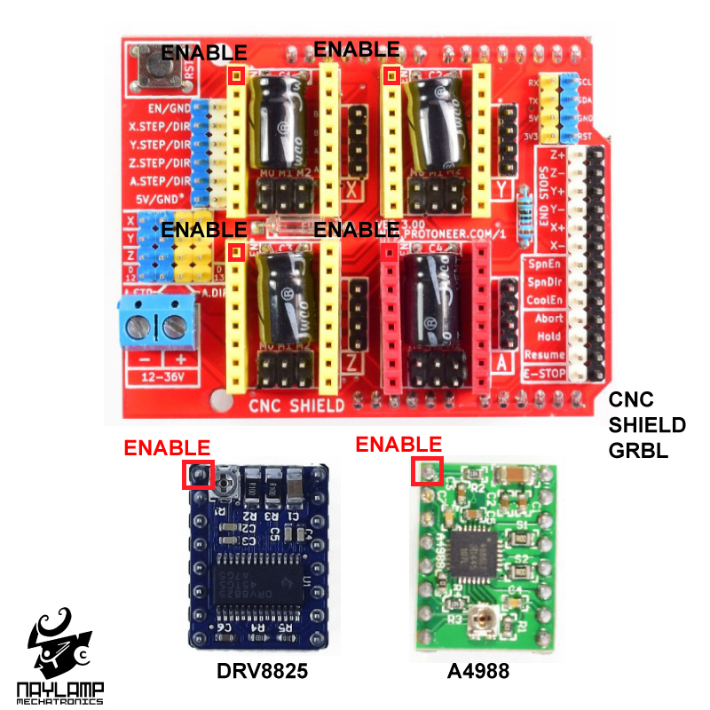
Construye tu CNC con la ayuda de este magnífico Shield. Compatible con Arduino Uno/Leonardo.
El Shield CNC GRBL v3.0 permite construir una máquina CNC de la manera más rápida y sencilla, solo necesitas agregar un Arduino Uno, unos cuantos Drivers pap A4988 o DRV8825 y una fuente de alimentación. Posee un diseño modular y Open Source. Compatible con GRBL que es un firmware OpenSource para Arduino que convierte código-G en comandos para motores Paso a Paso. Ideal para desarrollar proyectos como Router CNC, Cortadora Láser, Brazo robótico y hasta una Máquina Pick&Place.
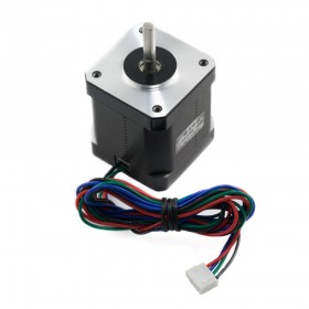
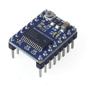
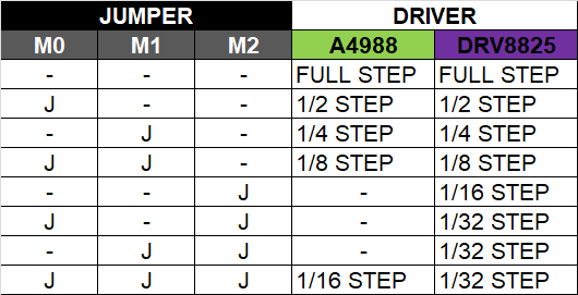
El shield CNC permite manejar 3 motores paso a paso (pap/stepper) de forma independiente (X, Y, Z) y 1 motor adicional (A) como duplicado de alguno de los anteriores. Es compatible con los drivers para motores paso a paso Pololu A4988 (Allegro) o los DRV8825 (Texas Inst.), el driver A4988 puede manejar motores paso a paso de hasta 2A por bobina y microstepping de 1/16, el driver DRV8825 es más versátil pues ofrece hasta 2.5A por bobina y microstepping de hasta 1/32. Podemos configurar de forma independiente la resolución de microstepping de cada driver con los 3 jumpers correspondientes.
Para energizar el shield podemos utilizar una fuente de alimentación DC entre 12 a 36 voltios. La capacidad de corriente de la fuente debe ser de aprox. 2 amperios por cada motor, entonces si utilizamos 4 motores necesitaremos una fuente de 8 amperios. Recomendamos utilizar la fuente de alimentación 12V/8.5A o 24V/5A. El voltaje de potencia no está conectado al pin de alimentación "Vin" del Arduino Uno, por lo que tendremos que utilizar una fuente separada para el Arduino o realizar un puente entre el voltaje de potencia y el pin "Vin" del Arduino Uno (máx. 12V)
El shield CNC es compatible con los siguientes modelos de Arduino: Arduino Uno R3 y Arduino Leonardo. Si deseamos utilizar otro microcontrolador o Arduino (Mega, Nano, etc), su uso debe ser como un módulo cableado y no montado directamente sobre el Arduino como un shield , esto debido a la disposición de pines utilizado en su diseño.
/*  FILE:    HC_CNC_Shield_Test
    DATE:    21/10/14
    VERSION: 0.1
    AUTHOR:  Andrew Davies

This is an example sketch which tests some of the functions of the Hobby
Components CNC shield (HCARDU0086). The sketch will step the X, Y Z, and Aux
stepper outputs in both directions. It will also report if any of the endstop
or control inputs have been triggered via the serial port.

WARNING: Ensure that your stepper motors are mechanically disconnected before
running this sketch as it will not stop drive to the motors should an endstop be
reached.

If you are using the Aux stepper output you will need to connect the pins labelled
D13 to A-DIR and D12 to A-STEP on the shield.

You may copy, alter and reuse this code in any way you like, but please leave
reference to HobbyComponents.com in your comments if you redistribute this code.
This software may not be used directly for the purpose of selling products that
directly compete with Hobby Components Ltd's own range of products.

THIS SOFTWARE IS PROVIDED "AS IS". HOBBY COMPONENTS MAKES NO WARRANTIES,
WHETHER EXPRESS, IMPLIED OR STATUTORY, INCLUDING, BUT NOT LIMITED TO, IMPLIED
WARRANTIES OF MERCHANTABILITY AND FITNESS FOR A PARTICULAR PURPOSE, ACCURACY OR
LACK OF NEGLIGENCE. HOBBY COMPONENTS SHALL NOT, IN ANY CIRCUMSTANCES, BE LIABLE
FOR ANY DAMAGES INCLUDING, BUT NOT LIMITED TO, SPECIAL, INCIDENTAL OR
CONSEQUENTIAL DAMAGES FOR ANY REASON WHATSOEVER.
*/


#define EN 8      /* Enable pin for all stepper outputs */

#define X_DIR 5   /* Direction pin for X axis */
#define X_STEP 2  /* Step pin for X axis */

#define Y_DIR 6   /* Direction pin for Y axis */
#define Y_STEP 3  /* Step pin for Y axis */

#define Z_DIR 7   /* Direction pin for Z axis */
#define Z_STEP 4  /* Step pin for Z axis */

#define A_DIR 13  /* Direction pin for Aux driver. Requires D13 and A-DIR pins to be shorted */
#define A_STEP 12 /* Direction pin for Aux driver. Requires D12 and A-STEP pins to be shorted */

#define X_ENDSTOP 9   /* X axis endstop input pin */
#define Y_ENDSTOP 10  /* Y axis endstop input pin */
#define Z_ENDSTOP 11  /* Z axis endstop input pin */
#define ABORT A0  /* Abort input pin */
#define HOLD A1   /* Hold input pin */
#define RESUME A2 /* Resume input pin */

int Count = 0; /* Counter to count number of steps made */
boolean Direction = LOW; /* Rotational direction of stepper motors */

/* The setup routine runs once when you press reset: */
void setup()
{
  /* Initialize serial */
  Serial.begin(9600);

  /* Configure the steper drive pins as outputs */
  pinMode(EN, OUTPUT);
  pinMode(X_DIR, OUTPUT);
  pinMode(X_STEP, OUTPUT);
  pinMode(Y_DIR, OUTPUT);
  pinMode(Y_STEP, OUTPUT);
  pinMode(Z_DIR, OUTPUT);
  pinMode(Z_STEP, OUTPUT);
  pinMode(A_DIR, OUTPUT);
  pinMode(A_STEP, OUTPUT);

  /* Configure the control pins as inputs with pullups */
  pinMode(X_ENDSTOP, INPUT_PULLUP);
  pinMode(Y_ENDSTOP, INPUT_PULLUP);
  pinMode(Z_ENDSTOP, INPUT_PULLUP);

  pinMode(ABORT, INPUT_PULLUP);
  pinMode(HOLD, INPUT_PULLUP);
  pinMode(RESUME, INPUT_PULLUP);

  /* Enable the X, Y, Z & Aux stepper outputs */
  digitalWrite(EN, LOW); //Low to enable
}

// the loop routine runs over and over again forever:
void loop()
{
  /* Count one step */
  Count++;

  /* If we have reached 500 steps then change the stepper direction and reset the counter */
  if (Count >= 500)
  {
    Direction = !Direction;
    digitalWrite(X_DIR, Direction); // Low = CW
    digitalWrite(Y_DIR, Direction); // Low = CW
    digitalWrite(Z_DIR, Direction); // Low = CW
    digitalWrite(A_DIR, Direction); // Low = CW
    Count = 0;
  }

  /* Step the X, Y, Z, and Aux motors */
  digitalWrite(X_STEP, HIGH);
  delay(1);
  digitalWrite(Y_STEP, HIGH);
  delay(1);
  digitalWrite(Z_STEP, HIGH);
  delay(1);
  digitalWrite(A_STEP, HIGH);
  delay(1);

  digitalWrite(X_STEP, LOW);
  delay(1);
  digitalWrite(Y_STEP, LOW);
  delay(1);
  digitalWrite(Z_STEP, LOW);
  delay(1);
  digitalWrite(A_STEP, LOW);
  delay(1);

  /* Check state of inputs */
  if (!digitalRead(X_ENDSTOP)) Serial.println("X-axis end-stop triggered!");
  if (!digitalRead(Y_ENDSTOP)) Serial.println("Y-axis end-stop triggered!");
  if (!digitalRead(Z_ENDSTOP)) Serial.println("Z-axis end-stop triggered!");
  if (!digitalRead(ABORT)) Serial.println("Abort input triggered!");
  if (!digitalRead(HOLD)) Serial.println("Hold input triggered!");
  if (!digitalRead(RESUME)) Serial.println("Resume input triggered!");
}
Gran selección de productos para fabricación digital aditiva, desarrolla tu creatividad
Por favor, regístrese primero.
RegistrarseCrear una cuenta gratuita para usar listas de deseos.
Registrarse